Why Build?
I had been researching mechanical displays facinated by the sounds of their rapidly firing mechanisms. I stumbled upon mechanical braille displays which supplied digital texts to the visually impaired. These are typically powered by piezo electric acutuators which deform in response to a current. While small and reliable these acctuators are expensive driving the price of a mechanical braille displays to upwards of a few thousand dollars. I decided to try to build my own for a more affordable price.
Design
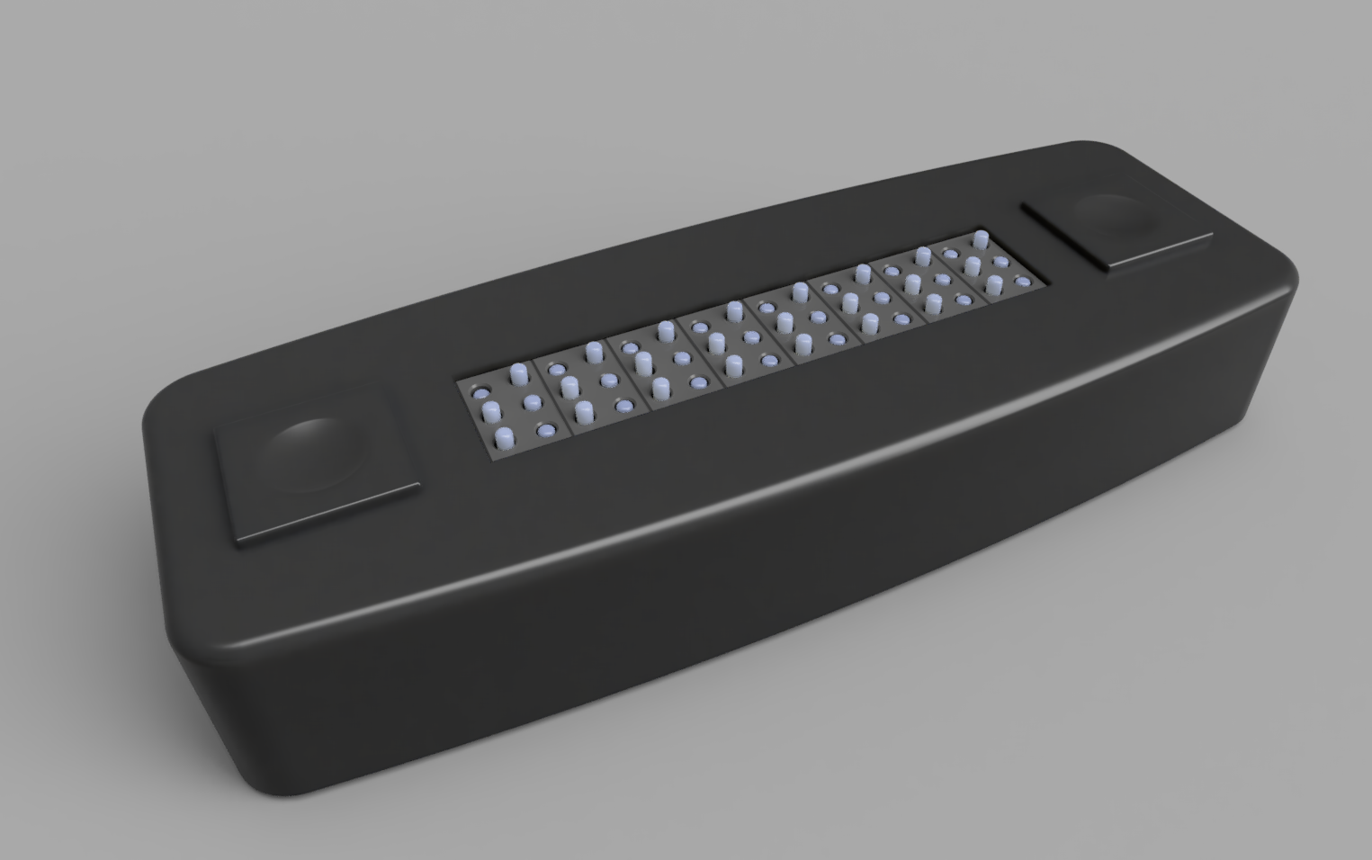
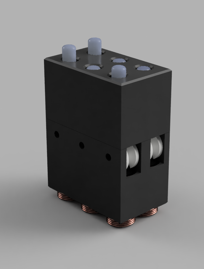
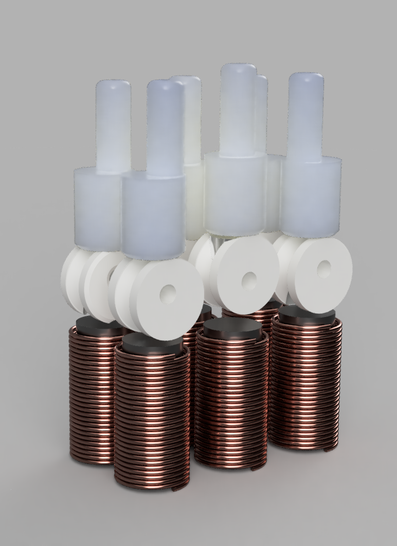
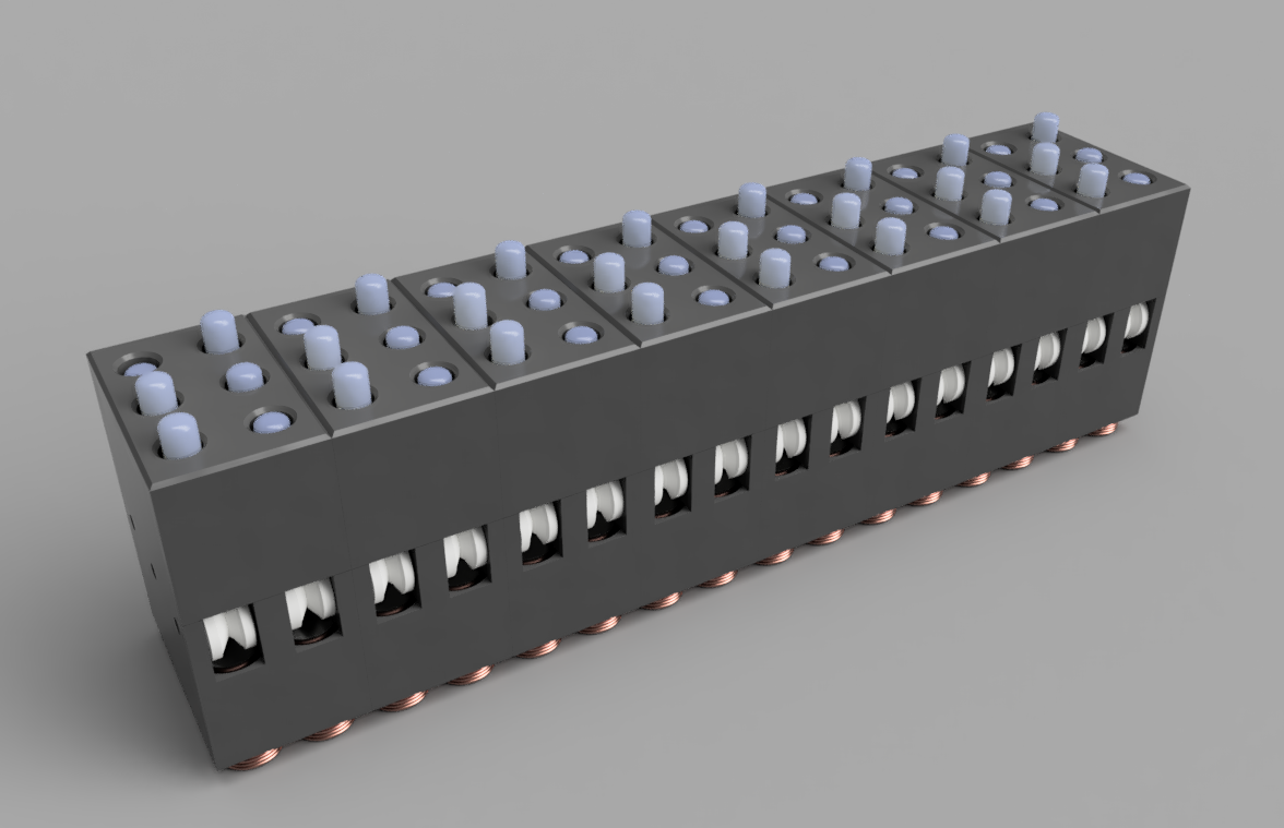
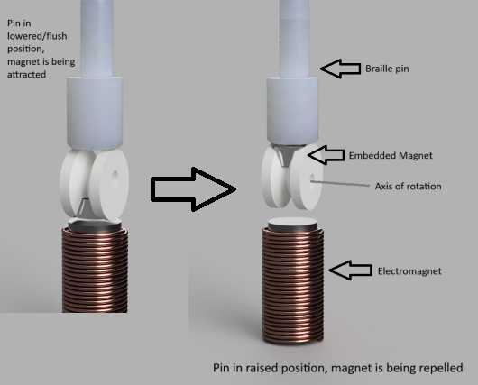
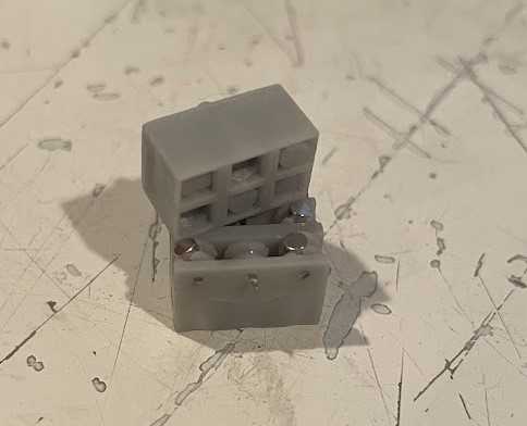
I settled on tiny electromagnets to power each braille pin in the 6 pin segments that comprised each letter, inspired by Vijay Varada’s design on hackday.io The electromagnets would rotate a tiny cam with an embedded magnet to push the pin up or down depending on the direction of current and thus the polarity of the electromagnet. This allowed the pins to resist downward pressure of a reading finger which a simple pin with a magnet would not. All of these tiny parts could be printed on my budget SLA resin printer.
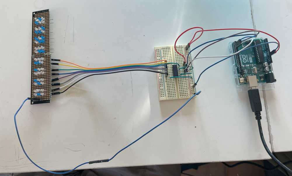
Next I needed to figure out how to power each of the 48 braille pins with an aurdino. I decided to treat them like LEDs in a matrix similar how those in the Jumbo 7 segment display I had built with my brother previously. After a bit of research I was attracted to shift registers which seemed a perfect IC for this project as they can control many pins with minimal inputs. Not having used shift registers before I soldered together a few LED arrays and learned the pin layout and control, which was made easy with the multitude of aurdino libraries avalible for shift registers.
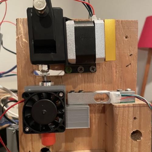
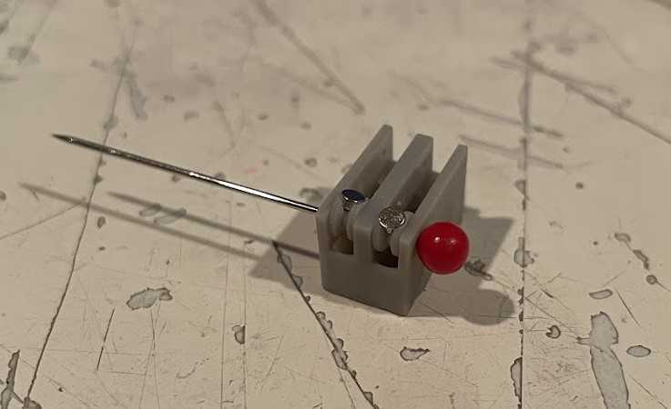
To understand the kind of power the tiny electromagnets would require I began testing electromagnets with various wire gauges, lengths, and number of turns on a simple test rig I printed. The copper wire was taken from old wall transformers I had laying around.
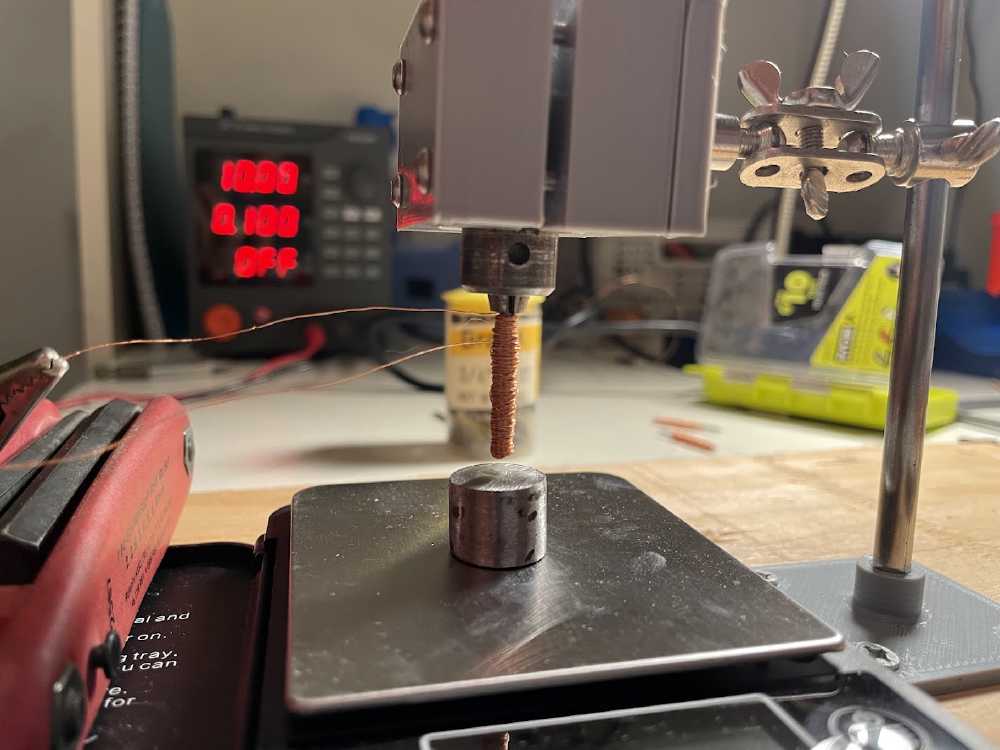
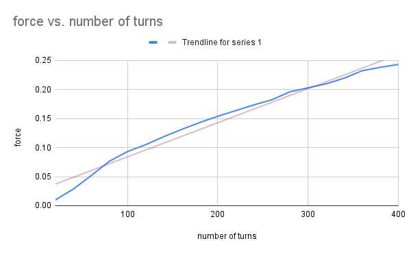
The elctromagnets were positioned at a constant distance above a small cutoff of steel rod. The scale could be balanced with the weight on it then when the electromagnet was powered using a variable power supply the |value on the scale * acceleration of gravity| = to the magnitude of force produced by the electromagnet. I determined that the ratio between number of turns of wire and force was approximately linear, as well as the relationship between force and current. This is in agreement with the equations for ideal electromagnets however I wanted to test it out of curiousity and also to see if the steel nails I was using would reach magnetic saturation, where the core cannot be further magnetized even with an increase in magnetic field. Later I learned that this only occurs at very high magnetic fields of around 1.6-2.2T for steel however.
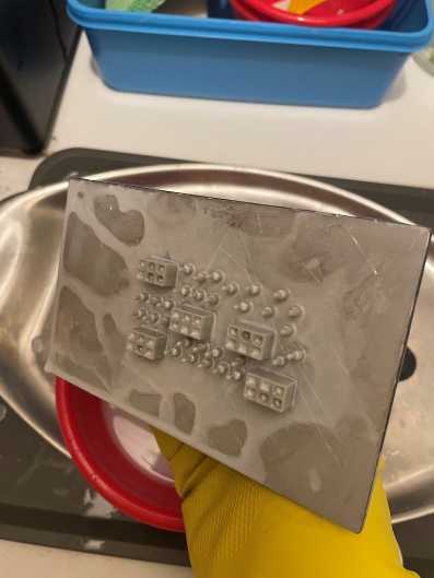
I began printing the cam and pins mechanism. They printed surprisingly well on upper layers, but the parts being incredibly small suffered greatly from “elephants foot” where the bottom layers are larger due to their over exposure. This over exposure is neccesary for them to stick to the build plate, so I needed to find an initial exposure time which would allow the parts to stick while also minimizing elephants foot. Still the issue persisted so I added chanfers to the bottom of the parts to minimize this. In the end the result was not perfect but only required minimal sanding to reach the desired dimentions.
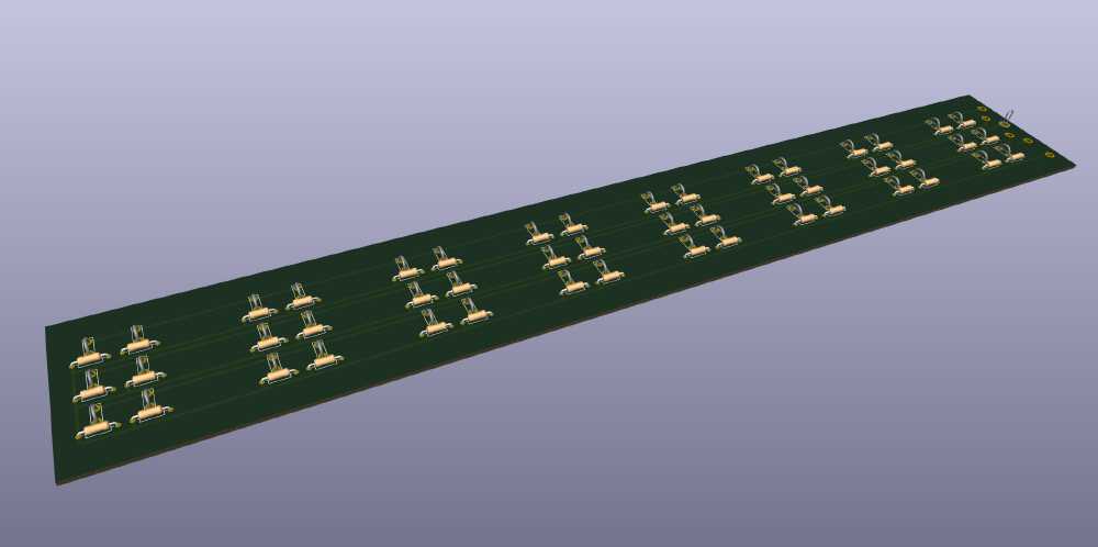
Back to electronics I watched some tutorials to learn KiCad to create some basic schematics although a little messy and a PCB layout with an array for the electromagnets to be soldered to.
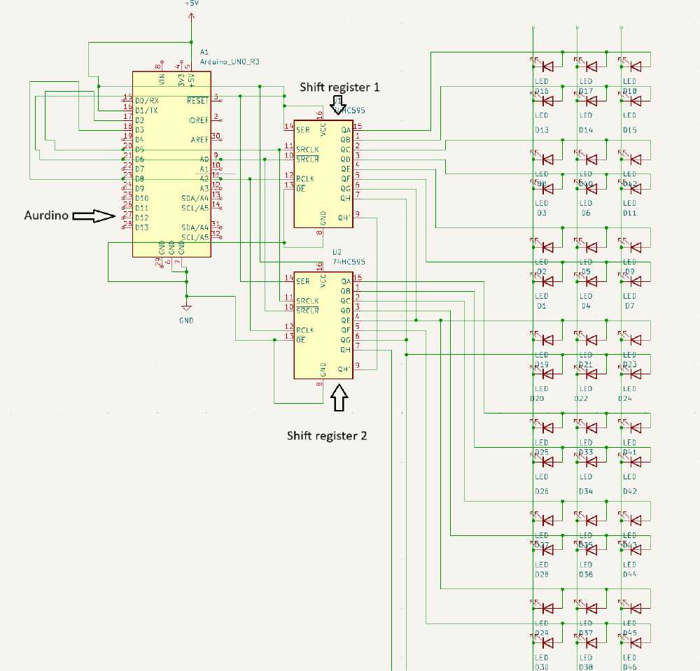
One awesome feature of shift registers is their ability to be chained together as shown in the schematic. This allows for 8 more bit or pins to be controlled with the same amount of inputs. There is no limit to how many can be chained together. Each column is controlled by an output of the shift register when one row is grounded. Then the secound and thrid rows can be grounded and the array is multiplexed by cycling this way. Unlike traditonal multiplexing only one cylce is needed due to the nature of the cam mechanisms requiring only a pulse to operate.
Currently I am continuing to optimize the cam mechanism, and finalizing the pcb layout to include through holes for soldering shift registers as well as transistors to serve as relays to deal with the higher current needed for the electromagnets.
Some more renders…