Purpose
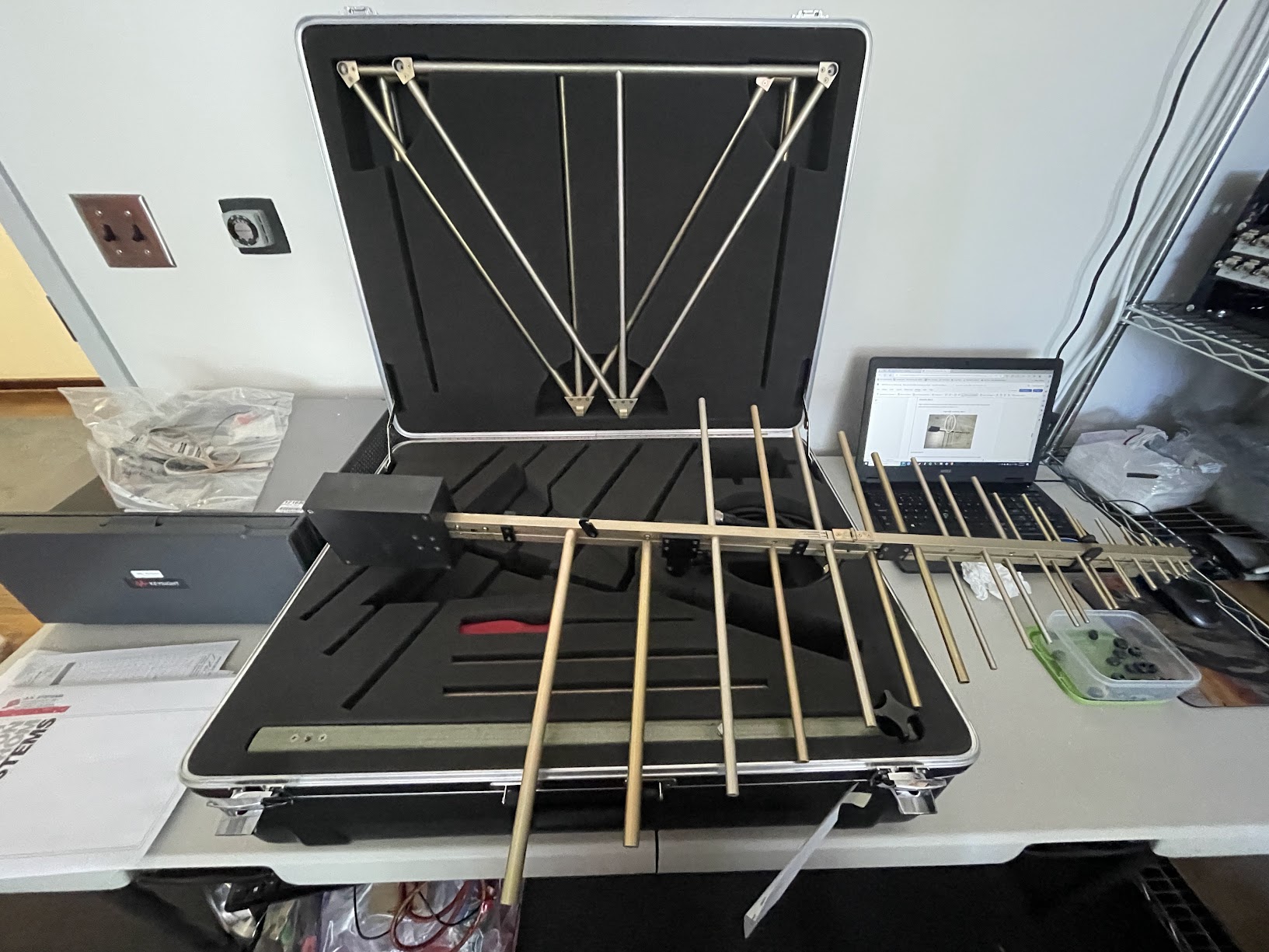
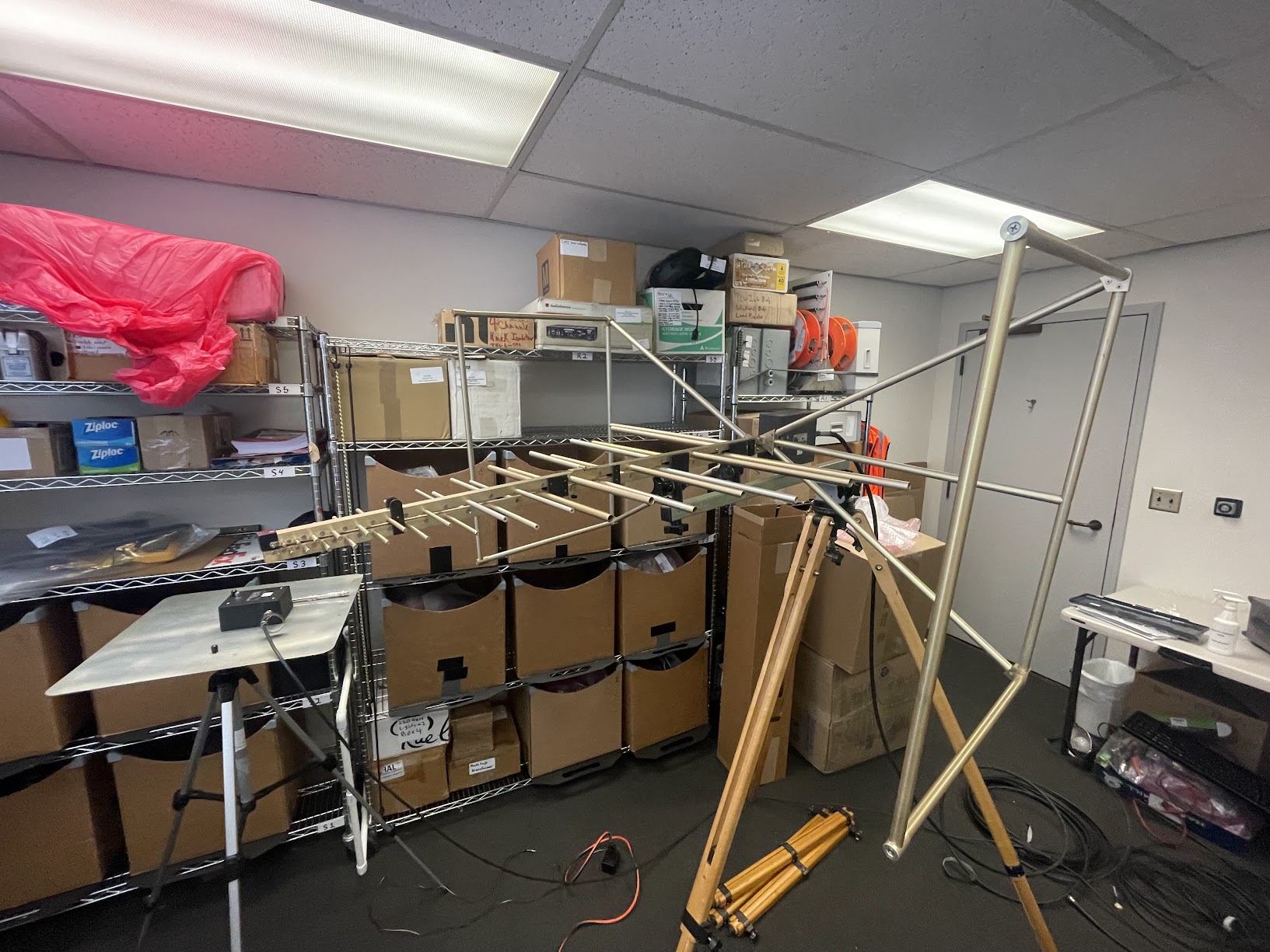
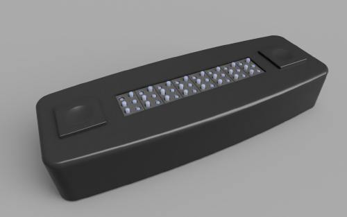
The testing teams in the field use various antennas to measure radiated emmitions for various jobs. For this project the team needed to test a wide range of frequencies so monopole, bi-logic, and horn antennas were used. Each has their own frequency operating range and needed to be calibrated with amplitude correction files (calibrated to resolve any discrepenices in that specific antenna and coax cable) and tested in the lab for a baseline.
Learning
Given realatively free reign over this complicated peice of equipment after I read the manual provided to engineers from Turner, I started experiementing with the various functions of the device.
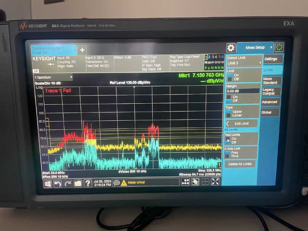
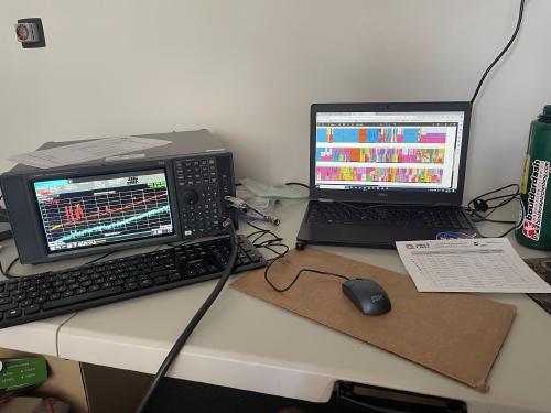
Typical operation for this application would include recording a trace of data. The spectrum analyzer or SA will take a sweep across all the ranges of frequencies specified in a given frequency band. Then higher amplitude spikes at different frequency levels can be noted and identified with the FCC radio table.
Here I used the bi-logic antenna measuring on band 5h (horizontal orientation of the antenna) and found peaks at around 75-100MHz as well as at around 175-200MHz. Identifying these in the FCC table we find that the first are FM radio and the next group is various TV broadcasting channels. Pretty cool if you ask me. I also found spikes for celluar data at 3G and 4G, AM radio, and lots of maritime mobile (communications between ships and coast stations or emergency dedications)